Hemodynamic Management
© B. Bo Sramek, Ph.D.
Contents
- 1 Hemodynamics
- 1.1 Blood Flow Parameters
- 2 Per-beat Hemodynamics
- 2.1 Per-beat and Per-minute Blood Flow
- 2.2 Per-beat Hemodynamic State
- 2.3 Related Per-beat Hemodynamic Parameters
-
2.3.1 Per-beat Vascular Resistance
2.3.2 Per-beat Left Stroke Work
-
3 Hemodynamics: The Dynamic Modulator
of Oxygen Transport
- 3.1 Hemodynamic Modulators
- 4 Hemodynamic Management[4]
- 4.1 Hemodynamic Map
- 4.2 Identification of Hemodynamic Modulators in Physiologic Terms
-
4.2.1 Vasoactivity
4.2.1.1 Map of Isolines of Vasoactivity
4.2.2 (Myocardial) Contractility
4.2.2.1 Map of Isolines of LSWI (Total Myocardial Contractility)
4.2.2.2 Identification of Contractility Modulators Representing
- 4.3 Hemodynamic Management Chart
- 4.4 Chronotropy - The Perfusion Blood Flow Modulation
- 5 Conclusion
- 6 References
Hemodynamics
Hemodynamics is a subchapter of cardiovascular physiology, which is concerned with the forces generated by the heart and the resulting motion of blood through the cardiovascular system[1]. These forces demonstrate themselves to the clinician as paired values of blood flow and blood pressure measured simultaneously at the output node of the left heart. Hemodynamics is a fluidic counterpart to the Ohm's Law in electronics: pressure is equivalent to voltage, flow to current, vascular resistance to electrical resistance and myocardial work to power.
The function of cardiovascular system is to deliver oxygen and nutrients to all tissues and to remove the by-products of combustion from the body. Human body can survive without solid food for weeks, without water for days, however, without oxygen just for seconds, since there is no long-term storage mechanism for this commodity. As a result, hemodynamics and its dynamic changes are mostly responding to dynamic demand for oxygen. Transport of oxygen is a blood flow and not a blood pressure-related phenomenon: Blood is the vehicle, oxygen is the cargo.
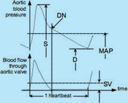
Fig.1: Aortic blood pressure and aortic blood flow over one heartbeat interval: S = Systolic blood pressure;
D = Diastolic blood pressure; MAP = Mean Arterial Pressure; SV = Stroke Volume; DN = dicrotic notch (aortic valve closure)
The relationship between the instantaneous values of aortic blood pressure and blood flow through the aortic valve over one heartbeat interval and their mean values are depicted in Fig.1. Their instantaneous values may be used in research; however, in clinical practice, their mean values, i.e., the MAP and SV, are adequate.
Blood Flow Parameters
Systemic (global) blood flow parameters are (a) the blood flow per heartbeat, the Stroke Volume, SV [ml/beat], and (b) the blood flow per minute, the Cardiac Output, CO [l/min]. There is clear relationship between these blood flow parameters:
CO
[l/min] = (SV
[ml] × HR
[bpm])/1000
{Eq.1}
where HR is the Heart Rate frequency (beats per minute, bpm).
Since the normal value of CO is proportional to body mass it has to perfuse, one "normal" value of SV and CO for all adults cannot exist. All blood flow parameters have to be indexed. The accepted convention is to index them by the Body Surface Area, BSA [m²], by DuBois & DuBois Formula, a function of height and weight:
BSA
[m²] = W
0.425[kg] × H
0725[cm] × 0.007184
{Eq.2}
The resulting indexed parameters are Stroke Index, SI (ml/beat/m²) defined as
SI
[ml/beat/m²] = SV
[ml]/BSA
[m²]
{Eq.3}
and Cardiac Index, CI (l/min/m²), defined as
CI
[l/min/m²] = CO
[l/min]/BSA
[m²]
{Eq.4}
These indexed blood flow parameters then exhibit normal range:
It is for the Stroke Index: 35 < SInormal < 65 ml/beat/m² and for the Cardiac Index: 2.8 < CInormal < 4.2 l/min/m².
The Eq.1 for indexed parameters then changes to
CI
[l/min/m²] = (SI
[ml/beat/m²] × HR
[bpm])/1000
{Eq.1a}
Per-beat Hemodynamics
The decision to name the global blood flow over a one-minute time interval the Cardiac Output goes back in time when actual CO was not routinely measured in clinical setting and the term probably had only a historical connotation ("at rest, the entire volume of blood within the cardiovascular system gets turned over once every minute").
That notion, to use CO - the per-minute blood flow - as a hemodynamically-significant parameter, got further reinforced by the first practical invasive techniques to measure the CO: The Fick Method (collection of data to calculate one CO value took approximately 5 minutes), or the Dye Dilution and Thermodilution techniques, which measure over a plurality of heartbeats a dye concentration or temperature value change over time in order to obtain one CO number. Major clinical problem with that approach is that CO (and, obviously, CI) already includes in its value the chronotropic compensatory effect by the HR as to maintain adequate body perfusion: For instance, the cardiovascular system of failing heart patients compensates for the lower SI value by an increase in HR, so they still end up with a "close-to-normal" value of CI and their bodies get adequately perfused.
A healthy body has its oxygen demand and oxygen delivery in equilibrium under any metabolic or physical load condition. The definition of Oxygen Delivery Index,
DO2I is:
DO
2I
[ml/min/m²] = CI
[l/min/m²] × 10 Hgb
[g/dl] × SaO
2 × 1.34
{Eq.5}
where Hgb is hemoglobin, SaO2 is saturation level of O2 in arterial blood and 1.34 is O2 affinity constant (1 g of Hgb binds 1.34 ml of O2)
Normal range of DO2I for adults is 495 < DO2I < 825 [ml/min/m²]
In a patient whose lungs are functioning normally (SaO2 ≥ 0.95) and who is not hemorrhaging or anemic (has a "normal" value of Hgb), the CI is thus the only dynamic modulator of DO2I. In such a patient CI parallels oxygen delivery.
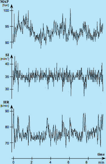
For such a healthy supine, resting adult the O2 demand is constant, the DO2I is constant and CI is constant, so their values as a function of time should be expressed as horizontal lines. Since CI = SI x HR, even graphical presentation of either SI or HR as a function of time should be a horizontal line. Fig.2, however, shows a major, continuous, per-beat variability of SI, HR and MAP values over time in such a patient. What is the explanation for this paradox?
Fig. 2: Simultaneous recordings of beat-by-beat values of HR (by ECG of Thoracic Electrical Bioimpedance device - TEBCO),
SI (by TEBCO) and MAP (by FinaPress) over a 10-minute period in a reclining, resting adult male. Courtesy of
David Shannahoff-Khalsa, The Research Group for Mind-Body Dynamics, Institute for Non-linear Science, University of California San Diego, California.
As expected, the beat-by-beat SI variations in response to respiration should be present: Inspiration, with negative intrathoracic pressure, increases venous return, thus the SI value, while expiration, with positive intrathoracic pressure, decreases it. These respiratory variations, having frequency of about ¼ of heart rate frequency and amplitude of about ± 1-2 ml/beat/m2, are clearly visible in Fig.2. Their are matched by opposite polarity and amplitude HR variation which would still maintain the CI value constant. Striking, though, are the large SI excursions, negative and random in appearance, taking place about every 20-150 seconds. These are the Mayer waves, representing the central nervous system’s reset signals to compensate for inability of cardiovascular biofeedbacks to have a DC transfer component within the biofeedback loop.
During the Mayer waves, the SI decreases momentarily by 20-30% from its mean value determined by the oxygen demand. This blood flow decrease is, however, immediately recognized. The hemodynamic response to a decreased SI is a chronotropic compensatory increase in HR, which purpose is to maintain CI, therefore DO2I, at a level in which O2 demand and supply are in equilibrium. You can clearly see that every Mayer wave-caused SI decrease is matched by a corresponding increase in HR, so the CI is maintained at the same level {Eq.1a}.
The maintenance of a constant value of CI in a resting, supine sleeping adult subject (having, obviously, constant oxygen demand) also exists over a longer period of time, as documented in Fig.3 in a 6-hour sleep study. Note that in spite of wild variations of SI (dreams?), the HR signal is, essentially, a mirror image of SI as to maintain the CI level and corresponding DO2I level constant.
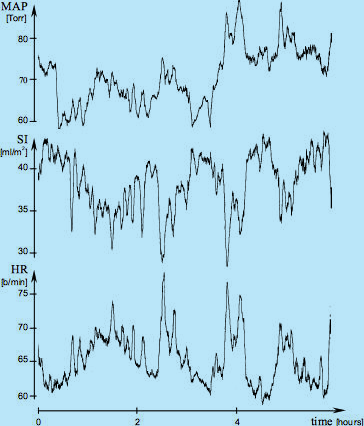
Fig.3: Sliding averages of MAP, SI and HR over a 6-hour period (courtesy of David Shannahoff-Khalsa,
The Research Group for Mind-Body Dynamics, Institute for Nonlinear Science, University of California San Diego, California).
The raw data were obtained in a beat-by-beat fashion during a sleep study and then subjected to the 200-beat sliding
average calculation and plotting. These recordings document that in addition to the dynamic, beat-by-beat adjustments of HR
to beat-by-beat variation of SI (as shown in Fig.2), the absolute value of HR continually adjusts to the
absolute value of SI as well, in order to maintain CI at a level providing an adequate perfusion blood flow.
One additional cardiovascular physiology conclusion from Fig.2 can be reached:
The (per-minute) Systemic Vascular Resistance Index, SVRI, defined as
SVRI = 80 × (MAP - CVP)/CI [dyn.sec.cm
-5.m
2]
{Eq.6}
where CVP is the Central Venous Pressure [mmHg];
The normal values are
[3]
MAP
normal = 85 mmHg; CVP
normal = 4 mmHg; CI
normal = 3.4 l/min/m²; resulting in
SVRI
normal = 1905 dyn.sec.cm
-5.m
2
is currently being used for assessment of afterload (vasoactivity): However, since SVRI utilizes CI (the mean value of blood flow over one minute) for its calculation, it renders the per-beat SI variations in Fig.2, invisible and thus assumes that SVRI in respect to beat-by-beat activity is a constant value parameter or a very slowly changing parameter. If this would be true, then the per-beat MAP recording in Fig.2 would have to be an image of SI [MAP ≈ SVRI x flow {Eq.6}] (blood pressure would have to copy the blood flow), though, as you can see from Fig.2, MAP is not an image of SI, leading to a conclusion, that the beat-by-beat variations of SI and MAP are accompanied and caused by an independent, beat-by-beat variations of vascular resistance. A new, per-beat parameter, therefore, has to be used for assessment of vasoactivity. It is called the Stroke Systemic Vascular Resistance Index, SSVRI (see Eq.7}.
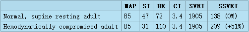
The clinical problem with utilizing SVRI for current assessment of afterload is documented in the following table.
The table has in the first row the normal hemodynamic and perfusion values (MAP, SI, HR and CI) for supine resting adults[3][4] with calculated normal values of SVRI and SSVRI. The second row has the same parameters for a hemodynamically compromised patient in the ICU: This patient is still normotensive (MAP = 85 mmHg [Torr]), however his hypodynamic state (SI = 31 ml/m²) is chronotropically compensated by increased HR (HR = 110 bpm) so the resulting CI still has the same normal value of 3.4 l/min/m² as for the normal patient. Should the clinician wishing to correct this hypodynamic state utilize SVRI to assess the status of vasoactivity, he would conclude that his vasoactivity is normal (SVRI = 1905, i.e.,the patient is normovasoactive), and would thus concentrate on therapies involving the two remaining hemodynamic modulators - volume and inotropy (probably choosing volume expansion and positive inotropic support). However, in spite of his expectations and to his surprise, this patient's hemodynamics would not improve, since the actual major cause of his compromised hemodynamic state, according to per-beat hemodynamics, is a 51% vasoconstriction. The true state of vasoactivity becomes visible only by using SSVRI for its assessment.
Per-beat and Per-minute Blood Flow
From the discussion above we can conclude that the hemodynamically-significant blood flow must be defined as the flow at the basic clock frequency of the cardiovascular system - a blood flow over one heartbeat interval, which is the SI, while the CI (a flow per-minute) becomes a perfusion-significant blood flow and should not be used for hemodynamic parameters calculations.
Per-beat Hemodynamic State
Hemodynamic state of a patient is defined by mean values of blood flow and blood pressure acquired simultaneously. The hemodynamic state parameters thus are the mean values of blood pressure and blood flow over one heartbeat interval, i.e., the Mean Arterial Pressure, MAP (mmHg = Torr) and the Stroke Index, SI (ml/beat/m²) (see Fig.1). The hemodynamics - acquiring and processingsimultaneously paired values of MAP and SI - thus becomes the per-beat hemodynamics.
Related Per-beat Hemodynamic Parameters
As stated above, the acquisition of hemodynamic state parameters (SI and MAP) and the calculation of related parameters, such as the vascular resistance and left myocardial work, have to be performed on aper-beat basis[2][4]
Per-beat Vascular Resistance
Per-beat Vascular Resistance is defined as the Stroke Systemic Vascular Resistance Index, SSVRI:
SSVRI = 80 × (MAP - CVP)/SI [dyn.sec.cm-5.m2]
{Eq.7}
where CVP is the Central Venous Pressure, 80 is a unit proportionality constant
SSVRI is calculated as the ratio of pressure difference across the systemic vasculature and the blood flow (an equivalent to electrical resistance -> R = V/I)
Per-beat Left Stroke Work
Per-beat Left Stroke Work is defined as the Left Stroke Work Index, LSWI where
LSWI = 0.0144 × (MAP - LAP) × SI [g.m/m
2]
{Eq.8}
where LAP is the Left Atrial Pressure, 0.0144 is unit proportionality constant
LSWI is calculated as the product of pressure gain across the pump and the blood flow (an equivalent to power in electronics W = V x I) and is equivalent of physical work expended by lifting up a weight (in grams) for 1 m, normalized by BSA.
Hemodynamics: The Dynamic Modulator of Oxygen Transport
The primary function of cardiovascular system is transport of oxygen. The task of the healthy cardiovascular system is to provide adequate perfusion to all organs and to maintain a dynamic equilibrium between oxygen demand and oxygen delivery. In a healthy patient it always increases blood flow in response to increase in oxygen demand. However, in a hemodynamically compromised patient, when the system is unable to satisfy increased oxygen demand, the blood flow to organs lower on the oxygen delivery priority list is reduced and these organs may, eventually, fail. Digestive disorders, male impotence, tiredness, sleepwalking, environmental temperature intolerance,..., are classical examples of a low-flow-state, resulting in reduced blood flow to the gut, sexual organs, skeletal muscles, skin...
The heart is both a variable frequency and variable volume pump, with a capability of increasing the perfusion blood flow (CI) in a young and healthy individual between the rest and peak physical exercise by 500%. Out of that, the variability of the heart frequency compensation (chronotropy) contributes to the increase of perfusion blood flow (CI) by approximately 300% (HR from 60 to 180 bpm), while the augmentation of stroke index (SI) increases the blood flow/beat contribution by approximately 70%.Please note that augmentation of SI takes place only for HR < 120 bpm; at HR ≈ 120 bpm, the heart becomes a constant volume pump.
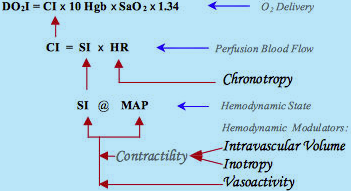
Fig.4: Schematic diagram of hemodynamic, perfusion blood flow and oxygen delivery modulation:
Combination effects of inotropes and/or intravascular volume determine the level of contractility.
Contractility and vasoactivity then form the Hemodynamic State (MAP @ SI).
Chronotropy, via HR modulation, establishes the perfusion blood flow (CI). CIthus is the dynamic modulator of oxygen delivery
Hemodynamic Modulators
This SI variability and, obviously, MAP variability, is accomplished through the activity of hemodynamic modulators.
The conventional cardiovascular physiology terms for the hemodynamic modulators are preload, contractility and afterload. They deal with (a) the inertial filling forces of blood return into the atrium (preload), which stretch the myocardial fibers, thus storing energy in them, (b) the force by which the heart muscle fibers shorten thus releasing the energy stored in them in order to expel part of blood in the ventricle into the vasculature (contractility), and (c) the forces the pump has to overcome in order to deliver a bolus of blood into the aorta per each contraction (afterload). The level of preload is currently assessed either from the PAOP (pulmonary artery occluded pressure) in a catheterized patient, or from EDI (end-diastolic index) by use of ultrasound. Contractility is not routinely assessed; quite often inotropy and contractility are interchanged as equal terms. Afterload is assessed from the SVRI value.
Rather than using the terms preload, contractility and afterload, the preferential terminology and methodology in per-beat hemodynamics is to use the terms for actual hemodynamic modulating tools, which either the body utilizes or the clinician has in his toolbox to control the hemodynamic state:
The preload and the Frank-Starling (mechanically)-induced level of contractility is modulated by variation of intravascular volume (volume expansion or volume reduction/diuresis).
Pharmacological modulation of contractility is performed with cardioactive inotropic agents (positive or negative inotropes) being present in the blood stream and affecting the rate of contraction of myocardial fibers.
The afterload is modulated by varying the caliber of sphincters at the input and output of each organ, thus the vascular resistance, with the vasoactive pharmacological agents (vasoconstrictors or vasodilators and/or ACE Inhibitors and/or ARBs)(ACE = Angiotensin-converting-enzyme; ARB = Angiotensin-receptor-blocker). Afterload also increases with increasing blood viscosity, however, with the exception of extremely hemodiluted or hemoconcentrated patients, this parameter is not routinely considered in clinical practice.
Please note that with the exception of volume expansion, which can be accomplished only by physical means (intravenous or oral intake of fluids), all other hemodynamic modulating tools are pharmacological, cardioactive or vasoactive agents.
Fig.4 describes the actual sequence of hemodynamic modulation (the arrows show the direction of the effects of modulation). There are only two major hemodynamic modulation contributors - contractility, related to the function of pump (modulated by the above-explained combined effects of volume ± inotropy), and vasoactivity, related to function of vasculature. The have mutually perpendicular hemodynamic effect on movement of the hemodynamic point, as it will be explained in detail in the following chapter.
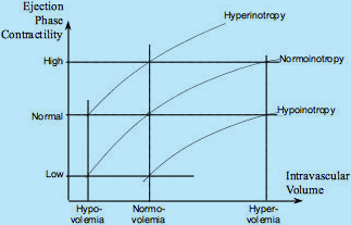
Fig.5 describes the relationship between the independent effects of intravascular volume (Frank-Starling, mechanical modulation) and inotropes (pharmacological modulation) on ejection phase contractility and, subequently, the MAP and SI values (see Fig.4).
Fig.5: The Frank-Starling Law and Inotropy: Three Frank-Starling curves shown for normoinotropy, hyperinotropy and hypoinotropy.
A patient, who is normovolemic and normoinotropic, exhibits normal level of Ejection Phase Contractility (EPC).
However, a patient who is hypovolemic can exhibit the same normal level of EPC if given positive inotropes,
and a patient who is volume overloaded (hypervolemic) can also have normal level of EPC if given negative inotropes
Fig.6 describes the timing considerations of hemodynamic modulation. Note that inotropes are the only modulators of contractility active during the isovolumic contraction, while the Frank-Starling (mechanical) control of contractility and afterload are ejection phase phenomena.
Fig.6: Timing considerations of working effects of preload, contractility (pharmacological = inotropes, and
mechanical = Frank-Starling mechanism, i.e., effects of intravascular volume) and afterload,
in respect to Systolic and Diastolic Time Intervals: Diastole = > Starts at S2-time and ends at Q-time.
Systole = > Isovolumic phase starts at Q-time, ends at AVO-time; Ejection phase
starts at AVO-time, ends at S2-time. (S2 = 2nd heart sound = aortic valve closure; AVO = aortic valve opening)
When the level of blood flow per beat (SI) is established through hemodynamic modulation, the chronotropic compensation then produces the perfusion blood flow (CI). Subsequently, CI, together with saturation level of arterial blood (SaO2) and hemoglobin (Hgb) enables calculation of global Oxygen Delivery Index (DO2I)(see {Eq.5}).
Hemodynamic Management[4]
is a clinical methodology, which
measures a patient's hemodynamic state, and
if an abnormal hemodynamic state is detected (as hypertension or hypotension and/or hyperdynamic or hypodynamic state), then
it identifies the causes of abnormal hemodynamics, i.e., the percentage deviation in hemodynamic modulators from their normal state (as hypovolemia or hypervolemia; hypoinotropy or hyperinotropy; vasoconstriction or vasodilation), and
administers a therapy with such cardioactive and/or vasoactive agents that negate the identified deviation while the percentage of the deviation determines the titration.
Note: Though the hemodynamic management rules are valid for all patients from neonates to geriatrics, we will use in all following examples just normal hemodynamic values for adults.
Hemodynamic Map
The best way to describe the hemodynamic state of a patient is to use graphical means: Similarly to a geographic map, where any place on earth is defined by two coordinates (latitude and longitude), the hemodynamic map uses for the coordinate system of a patient's hemodynamic state the blood flow value (SI) on the horizontal axis and the blood pressure value (MAP) on vertical axis (see Fig.7). The MAP scale can be divided in three horizontal bands (hypertension = MAP > 105, normotension = 70 < MAP < 105, and hypotension = MAP < 70) and the SI scale in three vertical bands (hypodynamic = SI < 35, normodynamic = 35 < SI < 65, and hyperdynamic blood flow = SI > 65). (For example: The hemodynamic state of a patient whose SI = 30 ml/m² and MAP = 130 mmHg is hypodynamic hypertensive).
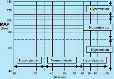
Fig.7: Hemodynamic map for supine, resting adults: SI is on the horizontal axis, MAP on the vertical axis.
A patient’s hemodynamic point is located at the intersection of coordinates of actual SI and MAP values.
Dot-and-dash lines mark the ideal hemodynamic values of SI = 47 ml/m2 and MAP = 85 mmHg = Torr.
Two sets of dash lines mark normal ranges of SI (35 < SI < 65 ml/m2) and MAP (70 < MAP < 105 Torr = mmHg).
Hypertensive, Normotensive and Hypotensive blood pressure bands, as well as Hypodynamic, Normodynamic
and Hyperdynamic blood flow bands are also marked, demarcating a total of nine classes of hemodynamic states.
Only one of them, a simultaneous Normodynamic and Normotensive state, called
the Normohemodynamicstate, is the desired hemodynamic state, the Therapeutic Goal.
As a result of three levels of MAP and three levels of SI, there are nine different classes of hemodynamic states, documented by nine rectangles in the hemodynamic map (Fig.7), where the hemodynamic point of a patient can land. Eight of them represent abnormal hemodynamic states and only one - a simultaneous normotension and normodynamic state (called the normohemodynamic state) - is the Therapeutic Goal.
The primary task of hemodynamic management is to identify such physiologic parameters, which correspond to, or parallel, the individual hemodynamic modulators in clinical terms.
Note: There is a generally accepted rule, that a ±20% deviation from the ideal value of any hemodynamic parameter is considered to be "normal", i.e. within the normal range due to a typical ±20% inaccuracy of measurement of blood flow.
Identification of Hemodynamic Modulators in Physiologic Terms
Vasoactivity
The determination of vasoactivity is, from the educational standpoint, a simple task, since it only involves arithmetic calculation.
The hemodynamic modulator corresponding to vasoactivity is the vascular resistance, which is calculated as a pressure difference across the systemic vasculature (MAP - CVP) divided by the blood flow (SI) (in electronics, resistance = voltage divided by current).
In the per-beat hemodynamics, the vascular resistance is the Stroke Systemic Vascular Resistance Index, SSVRI defined as
SSVRI = 80 × (MAP – CVP)/SI [dyn.sec.cm-5.m2]
{Eq.7}
The ideal value of vascular resistance - SSVRIideal - for supine, resting adults is calculated from ideal values of hemodynamic parameters for adults[3]: MAPideal = 85 mmHg; CVPideal = 4 mmHg; SIideal = 47 ml/m²; resulting in
SSVRI
ideal = 137.8 dyn.sec.cm
-5.m
2
{Eq.7a}
The percentage deviation from the ideal value is calculated as
% vasoactivity = SSVRI/SSVRI
ideal × 100
{Eq.7b}
where vasoconstriction takes place for SSVRI > SSVRIideal and vasodilation for SSVRI < SSVRIideal
The normovasoactivity is defined as 98.7 < SSVRI < 185.1. This range will be explained in Chapter 4.3 Hemodynamic Management Chart.
Map of Isolines of Vasoactivity (© Sramek)
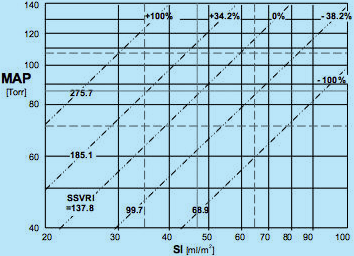
Fig.8: Hemodynamic map with isolines of vasoactivity plotted. The ideal normohemodynamic
state of MAPideal = 85 mmHg and SIideal = 47 ml/m2 is also shared with the ideal value
of vasoactivity SSVRIideal = 137.8 dyn.sec.cm-5.m2, marked as 0% deviation in vasoactivity from ideal.
Other isolines of vasoactivity plotted are: SSVRI = 185.1 (passing through ideal value of normotension MAPideal = 85
and low end of normodynamic flow SI = 35), marked +34.2%, i.e., 34.2% vasoconstriction;
SSVRI = 275.7 = > +100%, i.e. 100% vasoconstriction; SSVRI = 99.7 = > -38.2%,
i.e., 38.2% vasodilation; and SSVRI = 68.0 = > -100%, i.e., 100% vasodilation
The ideal value of SSVRIideal = 137.8 dyn.sec.cm-5.m2 is not only valid for the ideal normohemodynamic state (MAP = 85 @ SI = 47) but for all loci of MAP and SI values {Eq.7} that produce SSVRIideal = 137.8. Plotting all these loci in the Hemodynamic Map (see Fig.8) produces the isoline of ideal normovasoactivity - a straight diagonal line passing through the ideal normohemodynamic state - marked at one end SSVRI = 137.8 and at the other end 0%, denominating the zero deviation from ideal normovasoactivity.
Similarly, we can plot isolines for any deviation in vasoactivity from ideal. For instance, the SSVRI = 185.1 produces isoline of 34.2% vasoconstriction (185.1/137.8 = 1.342) and SSVRI = 275.7 represents 100% vasoconstriction. The same rule applies for SSVRI < SSVRIideal, which represents vasodilation: SSVRI = 68.9 describes 100% vasodilation (137.8/68.9 = 2).
Note that the relationship between the measured hemodynamic state and the corresponding vasoactivity state is bidirectional: For example, a patient with MAP = 105 and SI = 30: From the hemodynamic map in Fig.7, we can conclude the the patient is hypertensive hypodynamic, however, from the map of vasoactive modulation (Fig.8), we can deduce that since the patient's hemodynamic point (MAP = 105 @ SI = 30) landed on the isoline of SSVRI = +100% that the cause of his hemodynamic state in respect to vasoactivity is a 100% vasoconstriction. However, we can look at the modulating activity in the opposite direction: A 100% vasoconstriction will cause the hemodynamic state of the patient to attain any combination of MAP @ SI values, which will fall along the 100% vasoconstriction isoline, for instance MAP = 140 and SI = 40, or MAP = 71 and SI = 20...
The exact location of the hemodynamic point of a patient with 100% vasoconstriction discussed above on the isoline of 100% vasoconstriction is determined by the perpendicular vectorial activity of hemodynamic modulation of myocardial contractility, which will be discussed in the following chapter 4.2.2.2.
(Myocardial) Contractility
Contractility is the force by which the myocardial fibers shorten in time during systole. Contractility is a sum of two independent contributors working in tandem and affecting the contractile force:
Mechanical, represented by intravascular volume: Increased intravascular volume stretches more the myocardial fibers during the ventricular filling, thus storing more mechanical energy in them. More stretched fibers shorten with a higher force (Frank-Starling Law) thus increasing the contractility.
Pharmacological, represented by pharmacological agents circulating within the blood stream, called inotropes: positive inotropes increase icontractility, negative inotropes decrease it. Part of it has already been discussed in section 3.1 and Fig.5.
In order to identify the physiologic parameter, which defines (or parallels) myocardial contractility, we have to incorporate the following facts:
In respect to its timing, contractility involves the entire electro-mechanical systole and includes both the isovolumic and ejection phase (see Fig.6).
Essentially all myocardial O2 consumption takes place during the entire electromechanical systole, out of which about 75% is consumed during the isovolumic contraction, the remainder during the ejection phase.
Myocardial O2 consumption takes place to provide energy for physical work the myocardium performs.
Physical work by myocardium expended over one heartbeat interval is defined as the Left Stroke Work Index, LSWI = 0.0144 × (MAP - LAP) × SI (see {Eq.8})
We can, therefore, conclude that LSWI is a direct image of total myocardial contractility and thus represents the the sum of modulating effects of (volume ± inotropy).
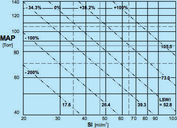
Map of Isolines of LSWI (Total Myocardial Contractility) (© Sramek)
Fig.9: Hemodynamic map with isolines of total myocardial contractility plotted.
This contractility is represented by the LSWI value. The ideal normohemodynamic
state of MAPideal = 85 mmHg and SIideal = 47 ml/m2 is also shared with the
ideal value of contractility LSWIideal = 52.8 g.m/m2, marked as 0% deviation in
contractility from ideal. Other isolines of contractility plotted are: LSWI = 39.3 (passing through the ideal
value of normotension MAPideal = 85 and low end of normodynamic flow SI = 35), marked -34.3%,
i.e., 34.3% hypocontractility; LSWI = 26.4 = > -100%, i.e., 100% hypocontractility; LSWI = 73.0
= > +38.2%, i.e., 38.2% hypercontractility; and LSWI = 105.5 = > +100%, i.e., 100% hypercontractility
Similarly to plots of isolines of vasoactivity described in Chapter 4.2.1.1, we can incorporate in the Hemodynamic Map the isolines of LSWI (see Fig.9).
The ideal value of LSWIideal = 52.8 g.m/.m² is not only valid for the ideal normohemodynamic state (MAP = 85 @ SI = 47) but for all loci of MAP and SI values {Eq.8} that produce LSWIideal = 52.8. Plotting all these loci in the Hemodynamic Map (see Fig.9) produces the isoline of ideal normocontractility - a straight diagonal line passing through the ideal normohemodynamic state - marked at one end LSWI = 52.8 and at the other end 0%, denominating the zero deviation from ideal normocontractility.
Similarly, we can plot isolines for any deviation in contractility from ideal. For instance, the LSWI = 73.0 produces isoline of 38.2% hypercontractility (73.0/52.8 = 1.382) and LSWI = 105.5 represents 100% hypercontractility. The same rule applies for LSWI < LSWIideal, which represents hypocontractility: LSWI = 26.4 describes 100% hypocontractility (52.8/26.4 = 2).
The normocontractility is defined as 39.3 < LSWI < 73.0. This range will be explained in Chapter 4.3 Hemodynamic Management Chart.
Please note that the relationship between the measured hemodynamic state and the corresponding contractility state is bidirectional. For example, we can derive from the hemodynamic map in Fig.9 the following information: The borderline hypotensive hypodynamic state of a patient with MAP = 69 and SI = 30, in respect tocontractility as its cause, is produced by 100% hypocontractility, or a 100% hypocontractility will cause the hemodynamic state of the patient to attain any combination of MAP @ SI values, which will fall along the 100% hypocontractility isoline, for instance MAP = 100 and SI = 20, or MAP = 61 and SI = 35...
However, we cannot determine at this point if the 100% hypocontractility is caused by a combination of (100% hypovolemia and normoinotropy), or (normovolemia and 100% hypoinotropy), or any linear combination of both, such, possibly, as (120% hypovolemia and 20% hyperinotropy),... This will be addressed and explained in the following chapter 4.2.2.2
Identification of Contractility Modulators Representing Inotropy and Volemia
Current invasive assessment of volemia is derived from the PAOP value (PAOP = pulmonary artery occluded pressure) in a catheterized patient with the flow-directed pulmonary (Swan-Ganz) catheter inserted, where PAOPideal = 9 mmHg is assumed to represent normovolemia. However, the relationship between volume and pressure in chambers is a result of an unknown chamber wall compliance. Volemia information obtained this way may, therefore, be skewed and is just an estimate and not theactual measurement of volemia.
For example, in an older patient with a stiff ventricle and PAOP = 6 mmHg, the diagnostic conclusion would be hypovolemia (PAOP = 6 < PAOPideal = 9). However, using subsequent volume expansion therapy in this patient to achieve the "normal" value of PAOPideal = 9 mmHg to achieve normovolemia, would result in a decrease of COindicating volume overload; use of PAOP to assess volume status has been in this case misleading.
This example describes another methodology for determination of volume status in a catheterized patient using the fluid challenge:
Measure CO(1)
Volume expand (for instance +100 ml) and measure CO(2).
If CO(2) > CO(1), = > the patient was previously hypovolemic, thus proceed with another fluid challenge...
When CO(n) < CO(n-1), = < patient has become hypervolemic = < administer diuretics...
The noninvasive assessment of volemia with ultrasound can be derived from the EDI value (End-Diastolic Index), however, since this methodology depends on determining the chamber volume from its planar images and, also, from the value of Ejection Fraction, EF [%], it cannot be considered to be an accurate "measurement" of volemia and is just its estimate.
There is, though, a direct, clear physiology-based determination of volemia status, based upon the following knowledge:
In Chapter 4.2.4 we have already explained how to determine the value of total myocardial contractility, a result of calculation of LSWI from MAP and SI measurement; we also know its normal value (normocontractility).
We also know that total contractility is the sum of modulating effects of (volemia ± inotropy)
Should we be able to directly measure the inotropic state and know its normal value (normoinotropy), then, from knowing the total contractility and the inotropic contribution to it, we could determine directly volemia by a physiology-based calculation.
Can we directly measure inotropy? The answer is YES:
We have already disclosed in Fig.6 that the isovolumic contraction is controlled only by inotropic state.
Isovolumic contraction is also the cardiac cycle phase which burns most of myocardial O2, while there is no blood flow associated with it (both the mitral and aortic valves are closed); it is related to gathering mechanical energy by a rapid, almost linear rise of intraventricular pressure. The intraventricular (dP/dt)max can, therefore, be considered a direct measure of inotropy (Normal inotropy would be defined as (dP/dt)max = 700 mmHg/sec). Unfortunately, this measurement can be accomplished only with a catheter having a pressure sensing transducer at its tip and placed into the left ventricle; this technique is used only for research purposes and is not common method in routine clinical practice.
The mechanical energy gathered during the isovolumic pressure rise is instantaneously released at the moment of aortic valve opening in the form of Left Ventricular Impulse, LVI. Since at this moment blood is not flowing yet out of the venticle, the LVI converts itself into the maximum acceleration of aortic blood flow, taking place in first 30 msec after aortic valve opening.
There are two noninvasive technologies available today that allow measurement of maximum acceleration:
Doppler ultrasound, which enables measurement of maximum acceleration of blood velocity at the aortic valve. This measurement is, though, operator-dependent (data are available only when the clinician holds the ultrasound probe aimed at the valve).
Thoracic Electrical Bioimpedance, TEB[5], as implemented in BoMed's TEBCO and HEMO SAPIENS' HOTMAN System), not only directly measures with adequate clinical accuracy the blood flow (SI, CI) but is continuous, hands-off and operator-independent. Since the bioimpedance image of aortic blood flow is (dZ/dt)/Zo (the first derivative of thoracic impedance change over time, normalized by total impedance), the TEB-measured inotropic state parameter, measuring the maximum acceleration of aortic blood flow (the second derivative of thoracic impedance change over time, normalized by total impedance) is called the Inotropic State Index, ISI, and is defined as
ISI = (d
2Z/dt
2)
max/Z
o [sec-2]
{Eq.9}
where Z
o is the Thoracic Base Impedance [Ω]
TEB uses the inverse parameter of Zo, called the Thoracic Fluid Conductivity, TFC [1/Ω = Ω-1], so more common version of Eq.9 is
ISI = (d
2Z/dt
2)
max × TFC
{Eq.9a}
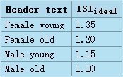
The ideal ISIideal value is gender and age dependent:
Hemodynamic Management Chart
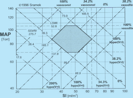
Fig.10: Sramek's Hemodynamic Management Chart for Resting, Supine Adults.
Hemodynamic Management Chart is formed by two superimposed orthogonal systems of coordinates:
(a) The Hemodynamic Map is formed by orthogonal system of MAP and SI.
(b) The Map of Hemodynamic Modulators also utilizes an orthogonal system of coordinates, however,
at a different plane; it is shown as two sets of mutually perpendicular diagonal lines representing vasoactivity
[marked in Italic] and contractility. Thepatient’s hemodynamic point (with coordinates of MAP @ SI) is shared by
both systems of coordinates. Its location within the map of hemodynamic modulators determines the status
of hemodynamic modulators responsible for the hemodynamic state. The gray hexagon defines the loci
of normohemodynamic states (the Therapeutic Goal). Detailed explanation of the Chart is in accompanying text
The Hemodynamic Chart is a graphical device implementing per-beat hemodynamics and hemodynamic management methodology discussed above. It enables to identify instantly the causes of observed abnormal hemodynamic state and administer corrective therapy as to reach the Therapeutic Goal, though the separation of effects of volume from the effects of inotropy has to be performed by additional means (for details, go to Chapter 4.2.2.2, Identification of Contractility Modulators Representing Inotropy and Volemia.
The map uses logarithmic scales both for horizontal and vertical axes. The Hemodynamic Map is a composite of two superimposed maps discussed above - Fig.8 (vasoactivity) and Fig.9 (contractility). The loci of normohemodynamic states = the Therapeutic Goal are depicted by gray hexagon area. The hexagon is demarcated in respect to hemodynamics by normal blood flow range (35 < SIideal < 65 ml/beat/m²) and by normal blood pressure range (70 < MAPideal < 105). Its demarcation in respect to hemodynamic modulators are vasoactivity and contractility isolines passing through the intersections of (SIideal-min = 35 and MAPideal = 85), and (SIideal-max and MAPideal = 85).
The map assumes the ideal values of CVP = 4 mmHg and PAOP = 9 mmHg used in Eq.7 and Eq.8.
It has also been implemented into the Slide Rule for Hemodynamic Management of Adults[6]
Locations and values of these demarcations are the true hemodynamic definitions of normal range of vasoactivity, defined as
99.7 < SVRIideal < 185.1
and normal range of contractility, defined as
39.3 < LSWIideal < 73.0.
Note that the hemodynamic effects of vasoactivity, represeneted by isolines of SSVRI, and hemodynamic effects of contractility, represented by isolines of LSWI,are mutually hemodynamically perpendicular to each other.
A therapy affecting contractility, i.e., involving manipulation with intravascular volume (volume expansion or volume reduction/diuresis) and/or manipulation with inotropic state (administration of positive or negative inotropes) will move the patient's hemodynamic point along the respective isoline of vasoactivity on which the therapy started.
A therapy affecting vasoactivity, i.e., involving manipulation with vasoactive agents (administration of vasoconstrictors or vasodilators/ACEI/ARB) will move the patient's hemodynamic point along the respective isoline of contractility on which the therapy started.
Chronotropy - The Perfusion Blood Flow Modulation
When the value of blood flow per beat (SI) is established through hemodynamic modulation, chronotropy is subsequent modulating activity with matches the current value of SI with a desired level of perfusion blood flow (CI) by adjusting the value of HR (see Eq.1a and Fig.4).
Normochronotropy is thus defined as
2.8 < CI < 4.2 l/min/m².
Chronotropy modulation is performed by administration of positive or negative chronotropes.
Note: In a majority of cases of detected abnormal hemodynamic state (for example, hypertension and hypodynamic circulation) accompanied with hypochronotropy, there is usually no chronotropic therapy needed, since the hemodynamic management-produced normohemodynamic state, resulting in increased SI value to its normal range, automatically takes care of the deviation in chronotropy.
Note: Whereas hemodynamic modulation has vectorial effects on the patient's hemodynamic point, chronotropic modulation is a scalar.
Note: Chronotropy is not related to the absolute level of HR and has no relationship to tachycardia or bradycardia. Chronotropy only describes how the compensatory effect of HR accomplishes the normoperfusion state.
Conclusion
Per beat hemodynamics and hemodynamic management methodology as implemented in HEMO SAPIENS' HOTMAN System has been used to manage hemodynamic disorders, such as hypertension, resistant hypertension or congestive heart failure, CHF, with significant improvements in outcomes[7],[8]. It clearly identifies the hemodynamic disorders' causes, and identifies for the corresponding therapy proper cardioactive or vasoactive drugs and their titration. Such Therapeutic Goal-oriented therapy then produces both normohemodynamic and nomoperfusion state, and allows to replace current trial-and-error drug selection management methodology with a straight line to reach the therapeutic goal.
References
WR Milnor: Hemodynamics, Williams & Wilkins, 1982
a b Sramek, Valenta, Klimes Editors: Biomechanics of the Cardiovascular System, 1995, Czech Technical University Press, ISBN 80-900054-3-8: 209-231
a b c Hurst JW. The Heart. McGraw Hill, 5th Edit, 1982:93
a b c BB Sramek: Systemic Hemodynamics and Hemodynamic Management, 2002, ISBN 1-59196-046-0
What is TEB and how it works
Slide Rule for Hemodynamic Management of Adults
Normohemodynamic Goal-oriented Therapy Improves the Outcomes
Treating Hypertension as a Hemodynamic Disorder Results in Three-fold Improvement in Outcomes